Proving Ground: Future GOES-R – Convective Initiation
Louie Grasso, Dan Lindsey and J. Braun
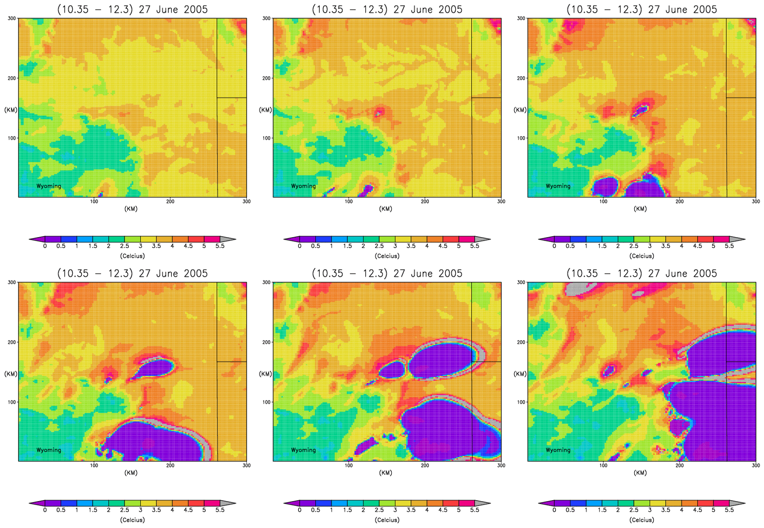
GOES-R ABI will have several channels in the window region from which channel difference products can be produced. Four channels, 8.5, 10.35, 11.2, and 12.3 µm can be differenced to produce a total of six difference images. Shown in Fig. 1 is a loop, every five minutes, of one such difference: 10.35 – 12.3 µm. This difference was produced from a numerical simulation of the 27 June 2007 thunderstorm event over Wyoming. Satellite imagery of numerical model output is termed “Synthetic” imagery.
Figure 1: Animated gif of brightness temperature differences between synthetic imagery at 10.35 and 12.3 µm. The loop shows images every five minutes, similar to the frequency of GOES-R.
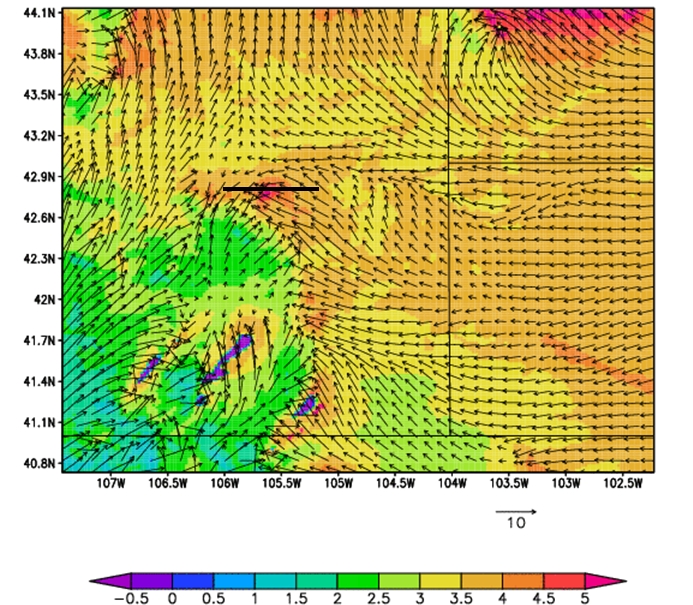
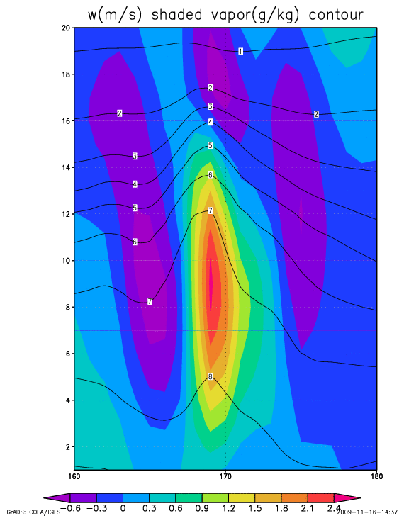
One advantage of a channel difference of synthetic imagery is to highlight the ability of a forecaster to identify regions where cumulus clouds, and eventually thunderstorms, may form. In the above loop, the precurser is the increase of positive values of the channel difference near the center of the image. Values are near 5 C prior to the development of convection. This signature was a consequence of the horizontal convergence (Fig. 2) of water vapor, which locally increased its depth within the boundary layer (Contours in Fig. 3). Water vapor is transported upward by positive vertical motion (Shaded region in Fig. 3).
Figure 2: Surface wind vectors plotted on a 10.35 – 12.3 µm difference image. Note the horizontal convergence associated with the 5 C difference near the center of the figure. The horizontal black line is the location of the cross-section in Fig. 3
Figure 3. Vertical cross section through the channel difference maximum (see Fig. 2). The cross section was taken in the east-west direction and shows the increased depth of the water vapor contours at x=170. Values of vertical motion are shaded every 0.3 m s-1.


